
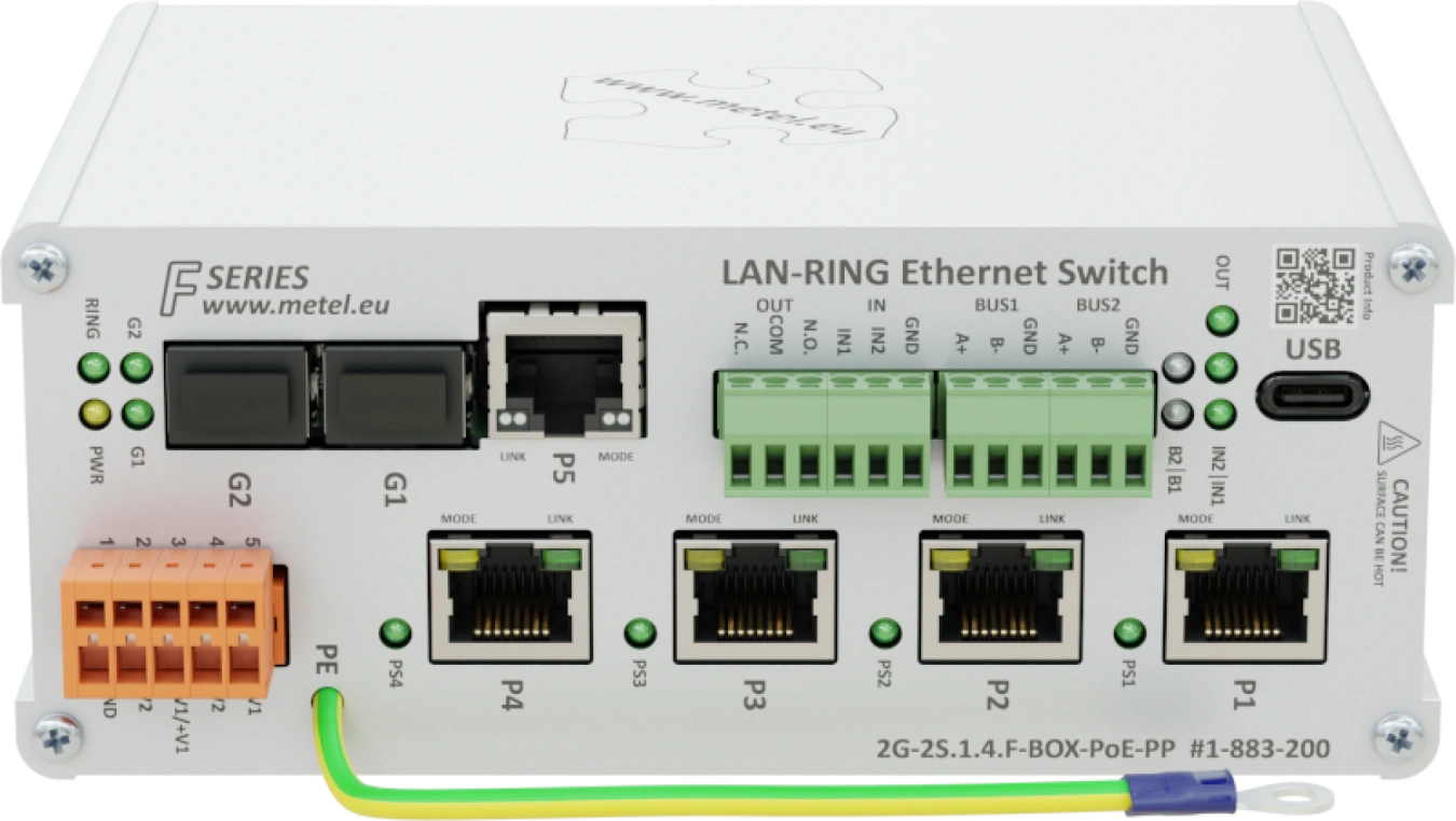
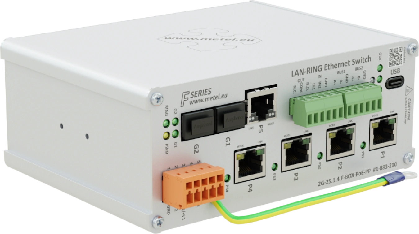
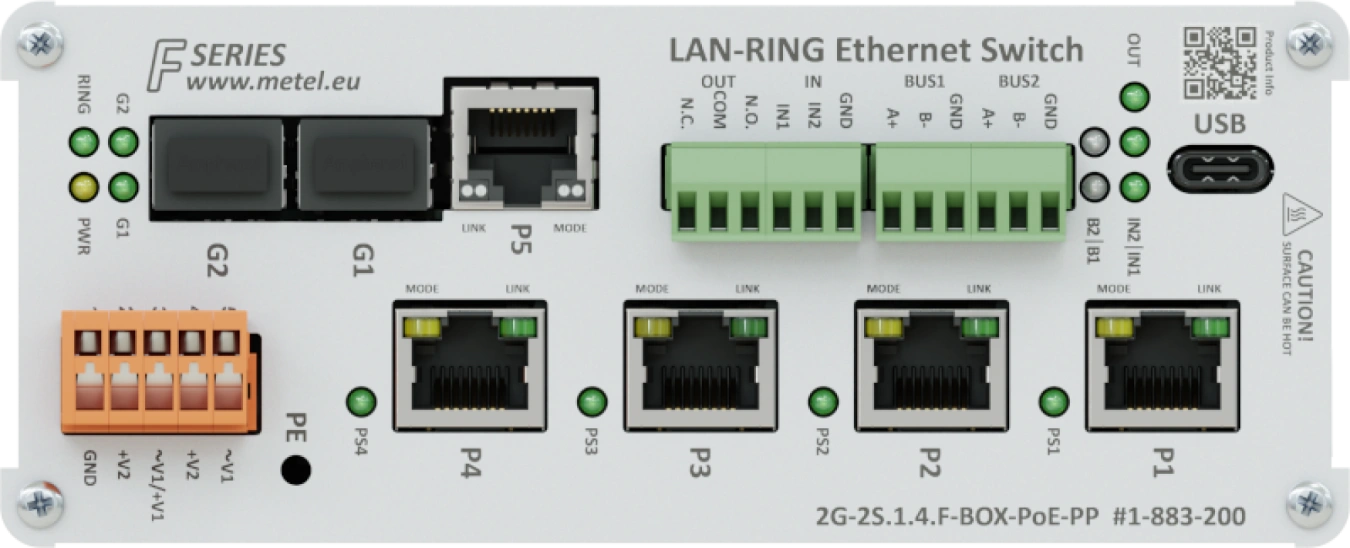
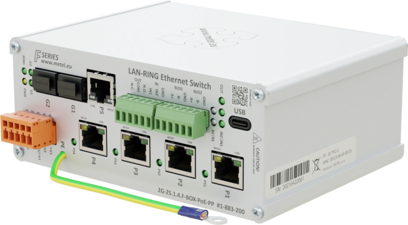
2G-2S.1.4.F
- 2x SFP slot with 100/1000BASE-X support
- 1x Gigabit ethernet port
- 4x Fast ethernet port with PoE, max. 95W per port
- Support UPOE, POH, 802.3af/at/bt, max. 95W per port
- Total PoE power through all ports is 170W
- 2x RS485 / Modbus-RTU
- 2x digital/alarm input
- 1x programmable relay output
- 2 independent power inputs
- Redundant topology LAN-RING, RSTP
- Event management with support for: HTTP/ONVIF client, E-mail, IP Watchdogs, ETH events, TCP, Modbus, DIO, balanced loops...
- VLAN, QoS, SNMP, SMTP, SNTP, IGMP, RSTP(-M), LLDP, 802.1X
- Overvoltage protection up to 1000A (8/20μs)
- Operating temperature from -40 °C to +75 °C
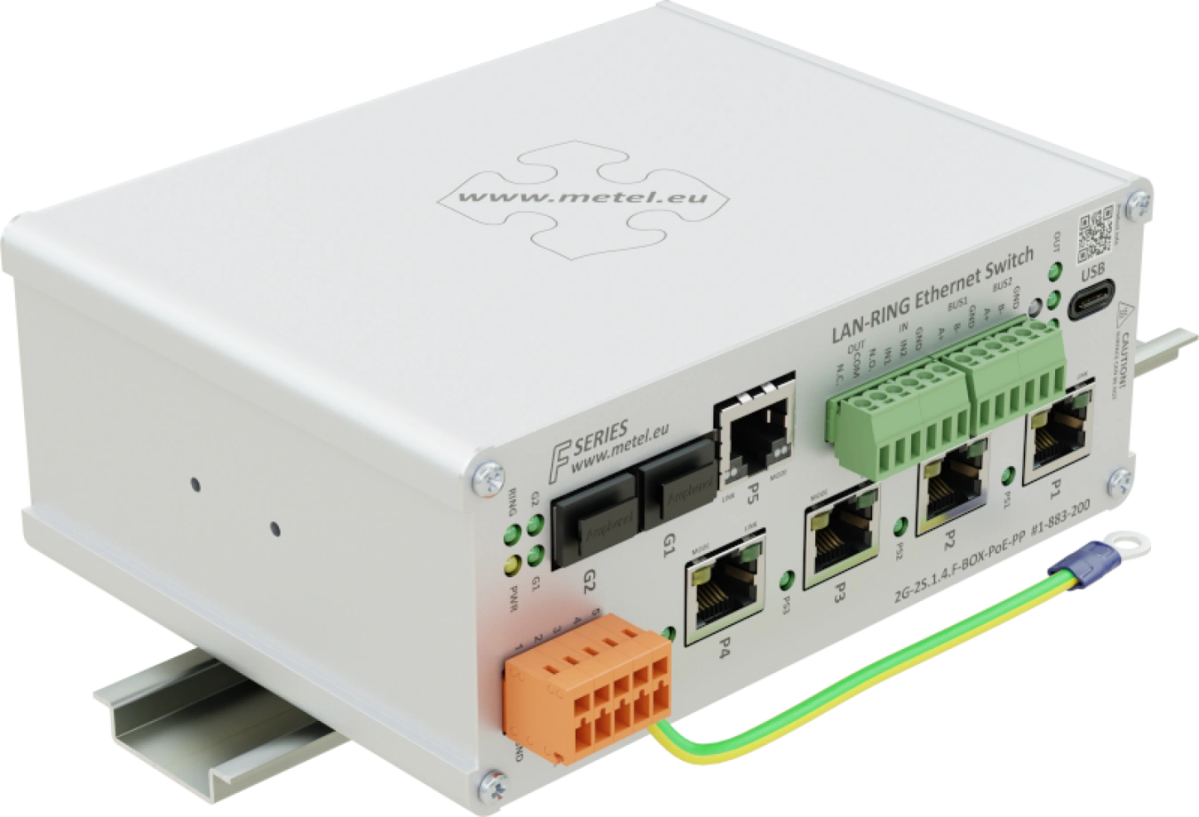
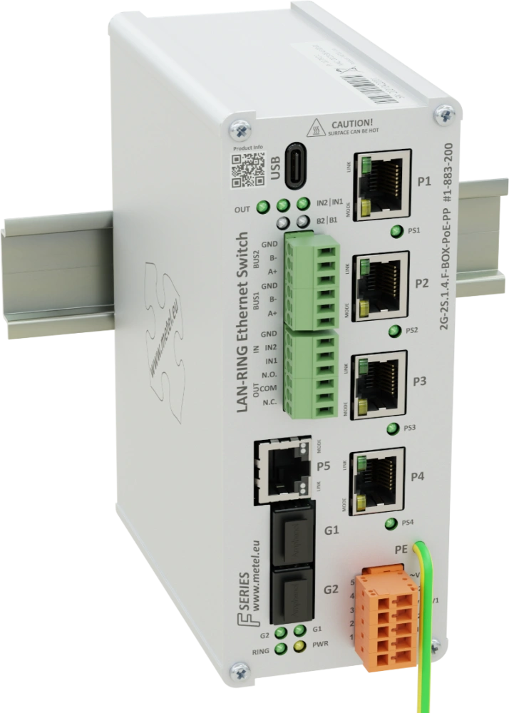
LAN-RING industrial managed PoE++ switches feature Ethernet ports, SFP slots as well as RS485 bus, digital/alarm inputs and relay outputs. Event management, which is part of the advanced management, makes these switches the ideal solution for applications with high demands on security and flexibility of the devices used. The switches support redundant MESH/RING topologies with up to 30 ms link recovery. Thanks to the highly resilient hardware, the switches can be deployed in a wide operating temperature range from -40 to 75 °C with a maximum PoE power of 170 W. All inputs and outputs are equipped with surge protectors, making the switches suitable for use in very harsh environments.
The switch is certified according to EN 50131-1 as a system bus transmission path for Asset(RS485), Galaxy(RS485) and MB-Secure (BUS-2). The devices are developed and manufactured in the EU and comply with NDAA requirements.
Models
2G-2S.1.4.F-BOX-PoE-PP
Industrial switch for circular topology with 2x SFP slot, 1x GE port, 4x Fast Ethernet port with PoE, support UPOE, POH, 802.3af/at/bt, max. 95W per port, maximum total PoE consumption across all ports is 170W, 2x DI with balanced loop support, 1x programmable NO/NC RELAY output, 2x RS485/1x RS422 BUS (MODBUS module support, TCP server, UDP mode), USB port for local management, redundant power input, 1000 A surge protection, EVENT MANAGEMENT. , operating temperature -40...+75 °C, VLAN, QoS, SNMP, SMTP, SNTP, IGMPv1/2, RSTP, LLDP, 802.1X.
Order code: 1-883-200
Availability: Full-scale production
Specifications
Technical parameters
| SFP SLOT | |
|---|---|
| Count | 2 |
| Supported formats | 100/1000 BASE-LX, BASE-BX |
| GIGABIT ETHERNET | |
|---|---|
| Count | 1 |
| Supported formats | 10BaseT, 100BaseTx, 1000BaseTx |
| Surge protection | 30 A waveform 8/20 μs |
| Connector | RJ45 |
| FAST ETHERNET | |
|---|---|
| Number of | 4 |
| Supported formats | 10BaseT, 100BaseTx |
| Surge protection | 1000 A waveform 8/20 μs |
| Protection class according to EN 61643-21 | C2 |
| C2 discharge current (8/20 µs) of core-PE | 1000 A |
| Connector | RJ45 |
| RS485 | |
|---|---|
| Count | 2 |
| Speed | max. 115200 bps |
| Surge protection | 30 A waveform 8/20 μs |
| DI/BI INPUT | |
|---|---|
| Count | 2 |
| Digital mode | NC / NO |
| Alarm mode | Analog 0 - 30 kΩ for balanced loops |
| RELAY OUTPUT | |
|---|---|
| Count | 1 |
| Type of contact | Switching |
| Max. Load | 62.5 VA (30 W) / 1 A / 60 V (resistive load) |
| POWER | |
|---|---|
| Count | 2 |
| Connector | WAGO 734-205 |
| Without PoE | 10 - 30 VAC / 10 - 60 VDC |
| With PoE up to 15.4 W | 48 - 57 VDC |
| With PoE+ up to 30 W | 52 - 57 VDC |
| With PoE++ up to 95 W | 53 - 57 VDC |
| Surge protection | 1500 W waveform 10/1000 μs |
| Power consumption | Max. 8 W without PoE |
| PoE | |
|---|---|
| Number of PoE ports | 4 |
| Max. power / port | 95 W |
| Maximum total power consumption of PoE | 170 W |
| Standard | IEEE 802.3af/at/bt, UPOE, POH |
| ENVIRONMENT | |
|---|---|
| Operating temperature | -40...+75 °C |
| Storage temperature | -40...+75 °C |
| Humidity | Max. 100% (non-condensing) |
| MECHANICS | |
|---|---|
| Weight | 0,65 kg |
| Dimensions - h / w / d | 60 x 150 x 126 mm |
| IP protection | IP 30 |
| Cooling | Passive |
| SECURITY | |
|---|---|
| Secure Booting | The code is stored and executed directly on SoC, therefore it is not externally accessible. |
| Firmware Upgrade | The FW image is encrypted and signed using AES-256, RSA-4096, SHA-512 |
| SNMP | SNMPv3 - SHA-512 / AES-256 (recommended) |
| SNMPv2c (obsolete) | |
| GUI Application | Digitally signed installation file using SHA-256, RSA 4096 |
| IEEE 802.1X-2004 | RFC3748 - EAP Packet Format, Authenticator PAE, Supplicant PAE |
| MANAGEMENT | |
|---|---|
| Application | SIMULand.v4 |
| SNMPv3 | Encrypted |
| SWITCH | |
|---|---|
| MAC address | 8 K |
| Max. frame size | 1632 B |
| Packet buffer memory | 1 Mbit |
| Switching | Store-and-forward, full wire-speed, non-blocking on all ports |
| Switching capacity | 6.8 Gbps |
Standards and protocols, EMC and safety
| EMC and safety | ||
|---|---|---|
| EN 55032 | EMC of multimedia devices - emission requirements | |
| EN 55035 | EMC of multimedia devices - immunity requirements | |
| EN 62368-1 | Safety requirements of Information technology equipment | |
| EN IEC 63000 | The Assessment Of Electrical And Electronic Products With Respect To The ROHS | |
| EN 61000-4-2 | 8 kV | Air discharge |
| EN 61000-4-2 | 6 kV | Contact discharge |
| EN 61000-4-3 | 20 V/m | Radiated RF field |
| EN 61000-4-4 | 2 kV | Bursty |
| EN 61000-4-5 | 2 kV | Shock pulses |
| EN 61000-4-8 | 30 A/m | Magnetic field |
| EN 61000-6-2 | Immunity - industrial environment | |
| EN 50130-4 ed. 2 | Alarm systems - Part 4: Electromagnetic compatibility | |
| EN 50121-4 ed.4 | Railway applications - EMC Emission and immunity of signalling and communication equipment | |
| EN 50131-1 | 4 | Alarm systems - system requirements |
| EN 50131-3 | 4 | Alarm systems - control panels |
| EN 61643-21 | Surge protectors in telecommunication and signalling networks | |
| EN 61000-4-11 | Short-term power dips and outages | |
| EN 61000-6-4 | Emissions - industrial environment | |
| Standards and protocols | |
|---|---|
| IEEE 802.3i | 10BASE-T 10 Mbit/s (1.25 MB/s) over twisted pair IEEE 802.3u for 100BaseT(X) and 100BaseFX |
| EEE 802.3u | 100BASE-TX, 100BASE-T4, 100BASE-FX Fast Ethernet at 100 Mbit/s (12.5 MB/s) with autonegotiation |
| IEEE 802.3ab | 1000BASE-T Gbit/s ethernet over twisted pair at 1 Gbit/s (125 MB/s) |
| IEEE 802.3z | 1000BASE-X Gbit/s ethernet over optical fiber at 1 Gbit/s (125 MB/s) |
| IEEE 802.3ac | Max. frame size 1522 bytes (allow 802.1Q tag) |
| IEEE 802.3af/at/bt | Power over Ethernet up to 15.4 / 30 / 90W |
| POH | Power Over HDBaseT (PoE up to 95W) |
| UPOE | Universal Power Over Ethernet (PoE up to 60W)) |
| IEEE 802.3x | Flow Control |
| IEEE 802.1p | Class of Service |
| IEEE 802.1X | Port-based Network Access Control (PNAC) |
| IEEE 802.1q | VLAN tagging |
| Modbus TCP | Master / Slave |
| Modbus RTU | Master / Slave |
| SNMP v2c/v3 | Protocol for managing devices on IP networks |
| IGMP v1/v2 | Internet Group Management |
| SNTP | Simple Network Time Protocol |
| SMTP | Internet standard for e-mail transmission across IP |
| RSTP | Protocol prevents creation of loops in the network |
| LAN-RING.v1, v2 | Ring topology with a very short time reconfiguration of max. 30ms |
| Management | GUI SIMULandv4 - USB C / Encrypted management via LAN |
Downloads
STEP models
Application notes
Manuals
Certificates
Catalogue sheets
Package contents
- Switch
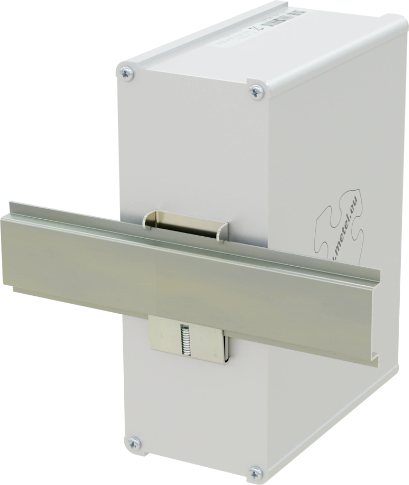
- Mounting kit for mounting the switch on a DIN rail
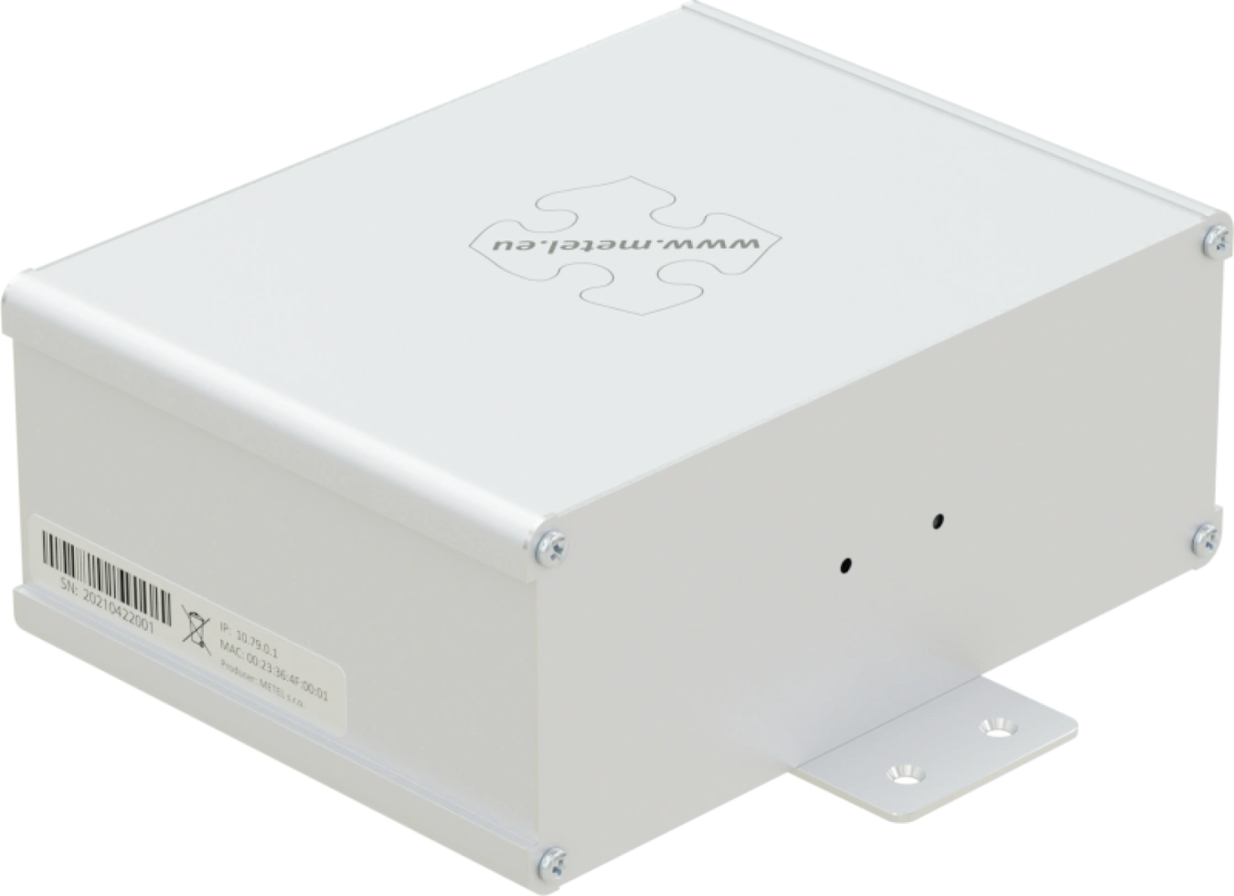
- Mounting kit for mounting the switch on a flat surface
- Installation manual
Accessories


The 19" SHELF-3U/IP-SU pull-out shelves are designed for fast and professional installation of LAN-RING industrial switches.

The 19" SHELF-4U/IP-SU pull-out shelves are designed for fast and professional installation of LAN-RING industrial switches.
FAQ
What are the default passwords?
SNMPv3 (read and write)
Username:"master"
Authentication algorithm: SHA1
Authentication password:"mastermaster"
Private algorithm: AES128
Private password:"mastermaster"
SNMPv3 (read only)
Username:"user"
Authentication algorithm: SHA1
Authentication password:"useruser"
Private algorithm: AES128
Private password:"useruser"
SNMPv2c (read and write)
Community:"write"
SNMPv2c (read only)
Community:"read"
How can I restore the switch to factory settings?
For security reasons, there is no reset button on the switches. If you need to reset the switch to factory settings, you will need a USB C cable (B - older models) and SIMULand.v4 configuration software.
Procedure
Click USB in the Conectivity menu, click Reset (Factory Default) in the following window and reset the switch to factory settings.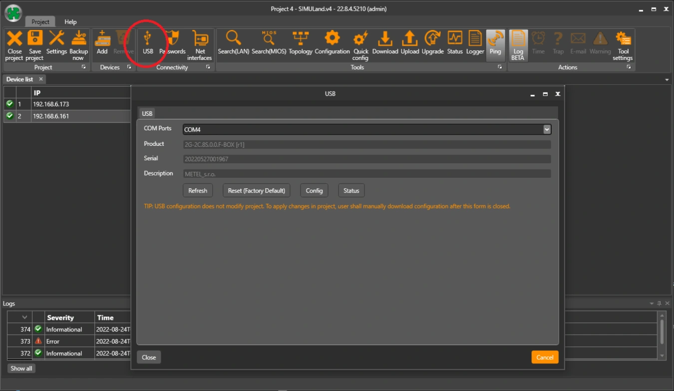
Note: For Windows 8.1 and earlier operating systems, you may need to install the USB driver.
Will the IP address, mask and gateway change after a factory reset?
Yes. A USB factory reset will restore the device to factory settings.
Default parameters
IP address - printed on the switch label
Mask - 255.0.0.0
Gateway - 10.1.0.1
Where can I find the latest firmware version for the F series switch?
In Simuland.v4, which always contains the latest firmware available for the switch.
After upgrading the switch, the switch will be set to its default settings, except for the IP, mask, gateway and ring.
Starting with FW 73.0000, the settings for BASIC, IP, Ports/PoE, Ports/VLAN, VLAN, Topology, Extension/ETH-BUS, Extension/BUS are remembered after the FW upgrade.
Will the configuration of the F-series switch be preserved after the FW upgrade?
Not really. After the switch upgrade, only the settings, IP, mask, gateway and ring will be preserved. The rest of the configuration will be default.
Starting with FW 73.0000, the settings for BASIC, IP, Ports/PoE, Ports/VLAN, VLAN, Topology, Extension/ETH-BUS, Extension/BUS will be remembered after the FW upgrade.
How is the compatibility of SFP modules from different manufacturers guaranteed ?
The mechanical and electrical parameters of SFP modules and slots are defined in the MSA (multi-source agreement). This ensures mutual compatibility between SFP module manufacturers and SFP slots of network elements. The SFP module includes an EEPROM. It stores information about the module type, supported speed, optical interface type, etc. The most widely used standards in IT are 100BASE-LX and 1000BASE-LX standards (LC connectors) with 2-fiber communication. This has probably also led to the fact that some commercial switches do not support the more modern single-fiber 100BASE-BX and 1000BASE-BX standards. Specifically, this refers to Byte 6 in the EEPROM (Ethernet Compliance Codes). For the above reasons, all BX-1000-...SFP modules have bit 1 (1000BASE-LX) set in Byte 6 and BX-1000-...SFP modules have bit 4 (100BASE-LX) set in Byte 6. The modules are then easily detected even by a switch that does not implement 100/1000BASE-BX support.
What do the W4 and W5 markings on SFP modules mean?
For modules with bidirectionaldata transmission over a singlefiber (wave multiplex), it is necessary to connect the optical modules correctlyto each other. Thismeans that, for example, inMETELWDM modules,the modulemarkedW4can only be interconnected with the modulemarkedW5. It is not possible to connect W4 with W4 or W5 with W5.
BX-100(0)-20-Wx-L
WavelengthsW4: TX:1310 / RX:1550 nm
WavelengthsW5: TX:1550 / RX:1310 nm
BX-10G-20-Wx
WavelengthsW4: TX:1270 / RX:1330 nm
Wavelengths W5: TX:1330 / RX:1270 nm
Does it affect how I insert SFP modules into SFP slots in the switch?
YES, ifyouare using the LAN-RING protocol. In terms of the LAN-RING protocol, the port with thelowerindex is thetransmitportand the port with thehigherindex is thereceiveport.Therefore,the rulemustbefollowedthat the optics will be connected from thelowerindex portto thehigherindex port.Therefore,inallswitchesin a ring,SFP modulesmustbeinserted in thesameway, e.g., an SFP with theW4 tag at the endwill be inserted into slot G1and anSFP with theW5 tag will be inserted into slot G2.
NO, ifyoudisable the LAN-RING protocol oruse the RSTP protocol. Inthiscase,it does not matter how the SFPs are inserted.
Do the SFP slots of LAN-RING switches also support SFP modules with RJ45 connectors?
Yes, they have support.
For example, we can recommend the following tested types:
MICROTIK S-RJ01
BEL SFP-1GBT-05
RJ45 SFP modules are not supported in the 2G-2C.8S.0.0.F(G)-BOX switch on ports P1-P8.
What encryption and authentication methods are supported on the switch for SNMPv3?
SNMPv3-enabled switches have SHA1 and AES128 methods enabled by default. You can change to SHA512 and AES256c in the configuration.
How to configure the RS485 bus for communication with HUB Pro?
The HUB Pro unit is connected to the RS485 bus of the METEL device (Switch, MiniLAN-4B2), which acts as a converter between the RS485 bus and the TCP/IP port (server). The additional software (client) then communicates with the HUB Pro via this port.
The TCP connection is established by the client, the first initialization must come from its side. The connection is then maintained automatically.
HUB Pro RS485 parameters (default):
Baud rate 9600b/s
Data bits 8
Stop bits 1
Parity None
Sample configuration: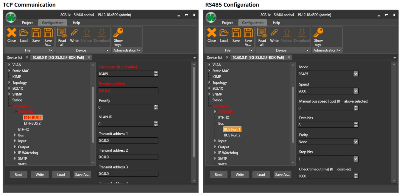
What is the maximum recommended load for 20G/2G/200M optical ports?
The recommended line load is 75% of the total data throughput.
Can LAN-RING also be used as a bus system?
Yes, of course, this option is available for the LAN-RING system. Only in this case, we recommend disabling the ringing function in the switch configuration (None) or switching LAN-RING to Rapid Spanning Tree Protocol (RSTP-M).
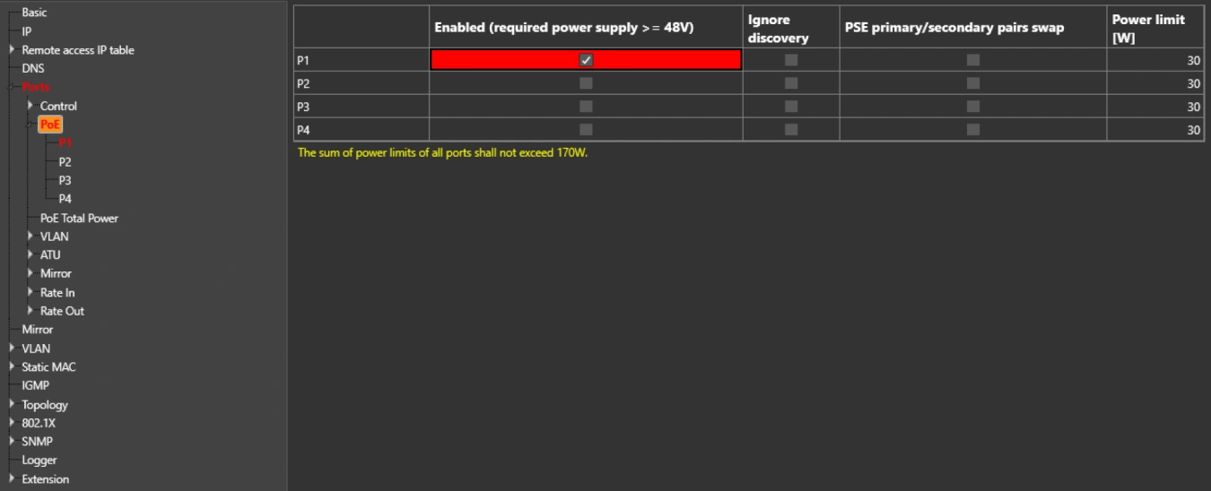
Is the PoE function available from the default settings of the switch?
The PoE function is factory set to "disable". Therefore, individual ports to which cameras or PoE-enabled devices are connected must be enabled in the configuration. If PoE does not start even after activation, the switch allows you to enable the Ignore Detect feature.
Extending UTP/FTP to more than 100 m?
If the distance between the camera and the switch is longer than 100 m, we use a LAN-EXT solution. This is a device that can repeat the route of the link, even several times in a row.
How to treat PoE camera freezes (IP Watchdog)
It is annoying to climb a pole and restart the camera or drive 100 km when the camera freezes. For this reason, we have added an IP Watchdog feature to the switches that monitors the camera address and automatically restarts PoE if communication is lost.
IP Watchdog is not only used to restart PoE, but can also monitor any IP address and in case of IP address failure, it can switch any contact in the LAN-RING network or trigger any other configured event.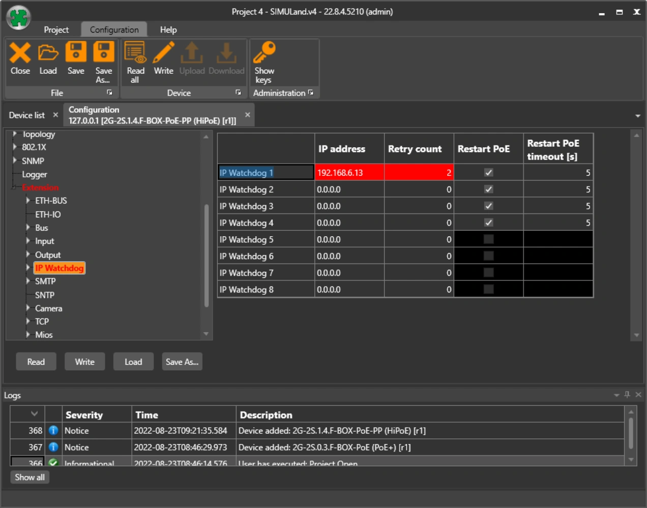
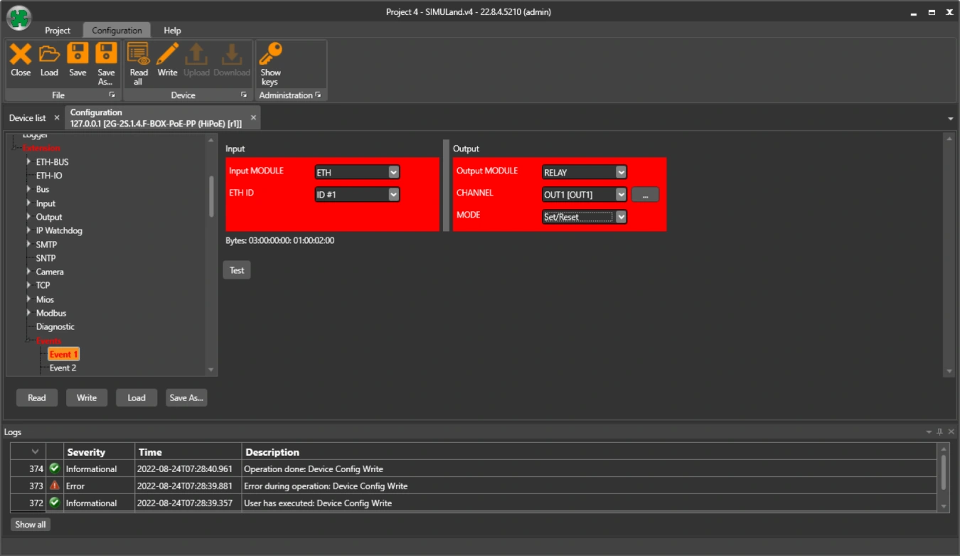
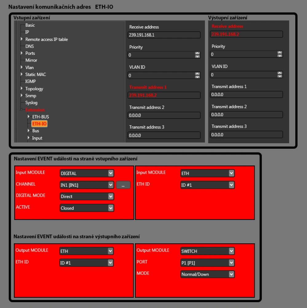
How to set the input status transfer to the remote relay?
ETH-BUS - communication addresses
On the device with relay you set the receiving address e.g. 239.192.168.1 (multicast) and on the device with input you set the sending address 239.192.168.1.
In this way, the input status information is transmitted to the output device.
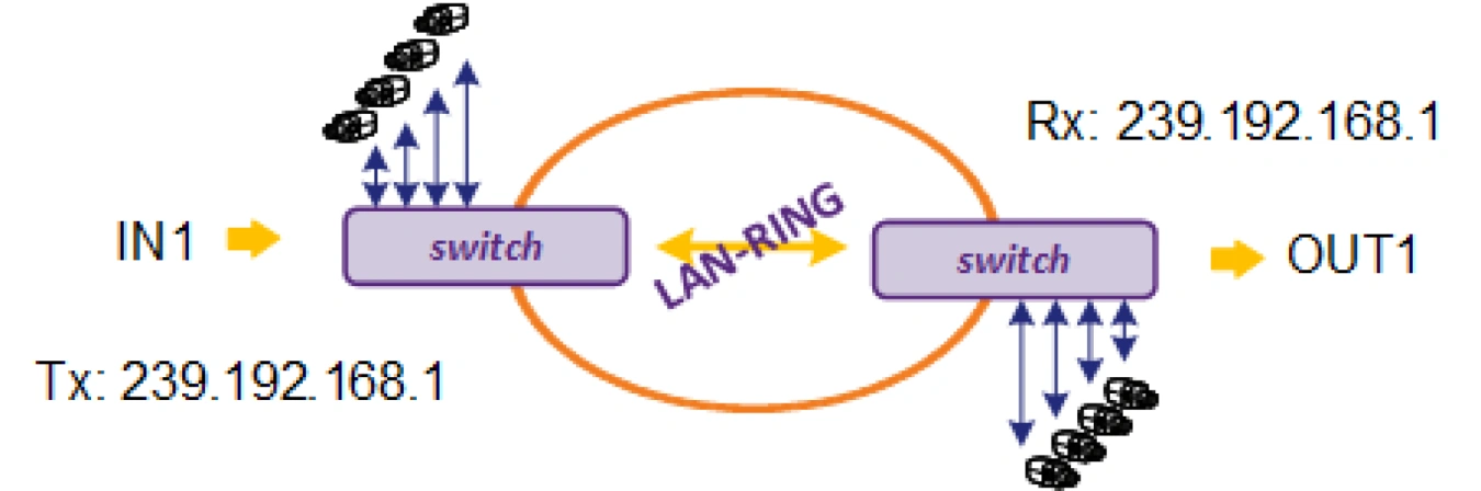
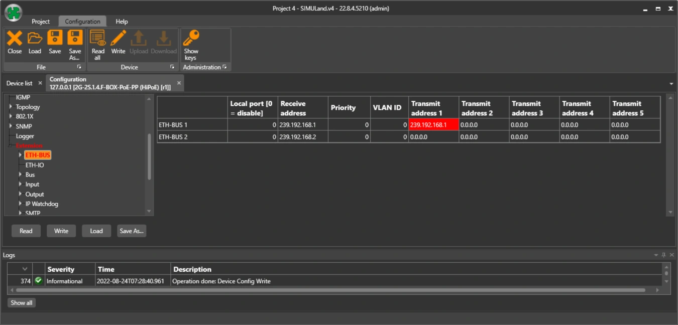
Create an event on the switch with input. Send the input status as an ETH event under ID#1.
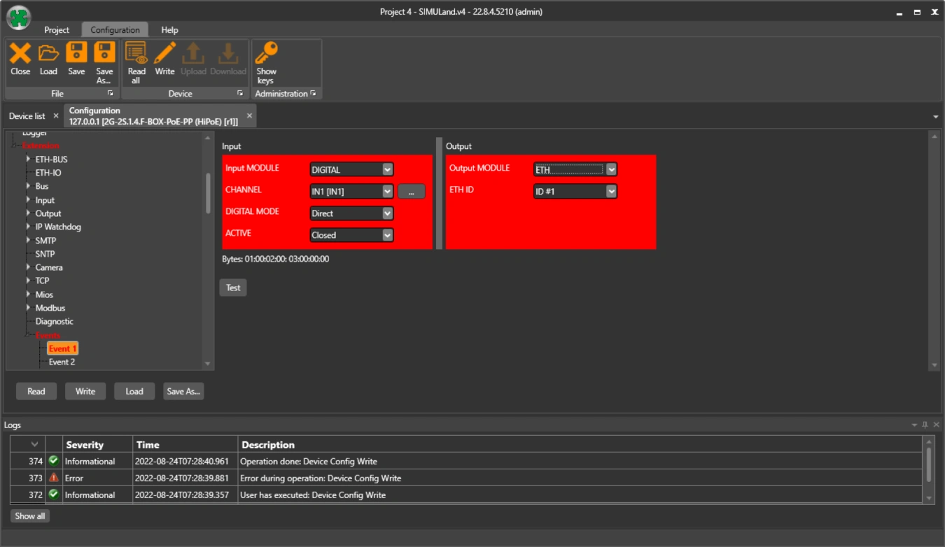
Establish a receive event on the switch with a relay. The response to the ETH event with ID#1 is to turn the relay on/off.
Different RSTP protocol behaviour
I have observed different RSTP behavior of your switch compared to a competing switch in the following situation. There are two switches in the network connected to each other by a fiber optic link. Egress filtering is enabled on one of these devices (Egress filtering: No unknown destination address). However, only one switch is available at this time because the link is blocked by the RSTP protocol. However, if I replace the unavailable switch with a competing device with a similar configuration, both switches are available.
Egress filtering causes BPDU frames to be sent only in one direction because the other direction is filtered. This causes the first switch to know about the second, but the second switch does not know about the first. This condition is handled by the so-called "contention mechanism". This was incorporated into the 802.1D-2004 standard and solves the problem you mentioned by blocking the link to prevent loops. Our implementation of the RSTP protocol complies with this standard. Other vendors may have a different implementation of the RSTP protocol based on an older standard that did not include a "dispute mechanism".
Is it possible to disable a switch port based on input from a remote device?
Yes, the switch allows you to respond to the input state of a remote device by data shutting down the port. PoE remains active, so there is no need to wait for camera initialization on recovery, it is available immediately.
Is it possible to use multiple data buses on one ring?
The number of transmitted data buses is limited only by the number of physical connection points. The buses are separated from each other by internal switch addressing. Each switch has so-called receiving and transmitting addresses through which it communicates with other switches. The configuration of these addresses is up to the user. In general, the number of buses is not limited, just beware of the response time, which in the LAN-RING system is 3.6 ms, and bus congestion. If you need to carry more buses in one location with one switch, miniLAN-4B2 converters are designed to expand the number of buses.
Solutions
- LAN-RING advantages
- Control of cameras by HTTP commands depending on digital input states
- EMC radiation and resistance tests
- LAN-RING - minimum requirements for optical path quality
- Redundant topology
- Without a clean connector your optics won't work
- Alarm inputs and outputs certified to EN 50131-1
- Backup power supplies certified according to EN 50131-1
- RS485 interface certified according to EN 50131-1
- Own development of CPU modules
- Filtering by source IP addresses
- IEEE802.1X
- Network segmentation
- Secure Boot
- SNMPv3