LAN-RING - minimum requirements for optical path quality
Update in progress
Below you can find an overview of the minimum requirements for the quality of optical routes in the LAN-RING system:
- All requirements are universally valid for all types of manufactured F and G series switches and media converters with METEL BX-100, BX-1000 and BX-10G series SFP modules.
- If METEL original SFP modules are not used on F-Series and G-Series switches and media converters, but third-party SFP modules are used, only the OTDR requirements apply.
| Basic parameters of METEL SFP modules | ||||||
| Type | Speed | Surface finish and grinding |
Wavelength Tx/Rx [nm] |
Number of threads | Range on SM/MM fiber [km] | Power/sensitivity [dBm] |
| BX-100-20-W4-L | 100Mb/s | SC/PC | 1310/1550 | 1 | 20/5 (OM3 and OM4) | -14 ~ -8 / < -32 |
| BX-100-20-W5-L | 100Mb/s | SC/PC | 1550/1310 | 1 | 20/5 (OM3 and OM4) | -14 ~ -8 / < -32 |
| BX-1000-20-W4-L | 1Gb/s | SC/PC | 1310/1550 | 1 | 20/2(OM4) | -9 ~ -3 / < -22 |
| BX-1000-20-W5-L | 1Gbps | SC/PC | 1550/1310 | 1 | 20/2(OM4) | -9 ~ -3 / < -22 |
| BX-1000-60-W4-L | 1Gbps | SC/PC | 1310/1550 | 1 | 60/- | -3 ~ +2 / < -22 |
| BX-1000-60-W5-L | 1Gbps | SC/PC | 1550/1310 | 1 | 60/- | -3 ~ +2 / < -22 |
| BX-10G-20-W4 | 10Gb/s | LC | 1270/1330 | 1 | 20/- | -2 ~ +2 / < -14 |
| BX-10G-20-W5 | 10Gb/s | LC | 1270/1330 | 1 | 20/- | -2 ~ +2 / < -14 |
Failure to comply with these requirements may result in a significant reduction in link quality or even make the link unavailable. Insufficient optical path quality usually results in:
- TCP communication - In TCP communication, the TCP client first establishes a connection with the server, which acknowledges receipt of the data. if the packet is corrupted or lost, the client resends it. As the number of errors increases. the load on the network increases. which can lead to network congestion.
- UDP communication - unlike TCP communication. the counterparties do not establish a connection and the receipt of data is not acknowledged. Packet corruption or loss is manifested in multicast clients by, for example, randomly appearing links within
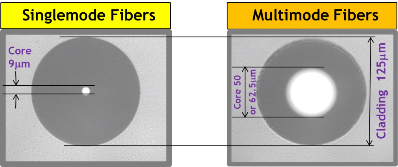
Supported fiber optic types
All BX100 and BX1000 series fiber optic connectors are universally applicable on all fiber types listed below.
| Type | Core/sheath diameter | Type |
BX-100 Series |
BX-1000 Series |
BX-10G series |
| Multimode | 50/125 µm | OM2-4* | Compatible | compatible | - |
| 62.5/125 µm | OM1* | compatible | compatible | - | |
| Single-mode | 9/125 µm | OS2 | Compatible | Compatible | compatible |
| * Particularly for OM1 and OM2 types, consider the bandwidth, which is limiting for transmission over longer distances. See Bandwidth | |||||
Optical fibre bandwidth
The bandwidth specified in MHz/1km limits usability, especially for older OM1 and OM2 multimode fibre types. The following table shows the maximum ranges for different data rates and fibre types.
| Ethernet |
OM1 - 62,5/125µm multimode |
OM2 - 50/125µm multimode |
OM3 - 50/125µm multimode |
OM4 - 50/125µm multimode |
OS2 - 50/125µm single-mode cable |
| 100Mb/s | 2000m | 2000m | 5000m | 5000m | 20km |
| 1Gbps | 550m | 550m | 1000m | 2000m | 20/60km |
| 10Gb/s | 300m | 300m | 300m | 300m | 20km |
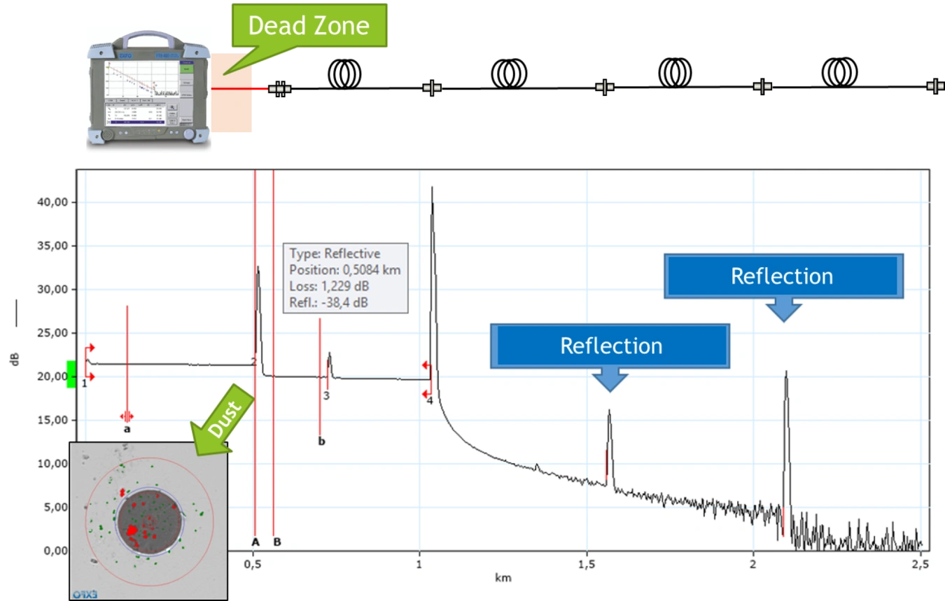
OTDR - attenuation of reflections in joints and welds
Before installing active elements, we recommend measuring all optical paths using the OTDR method. Measurements should be taken from both sides and with the fiber forward to eliminate the dead zone of the OTDR analyzer. Measurements using this method will provide information on:
- the total attenuation of the optical path
- attenuation of all welds, splices and other connections
- the exact location of all welds, splices and possible faults on the routes
- the attenuation of the optical fibre and its distribution along the route
- the length of the routes
- fibre inhomogeneity
- the continuity of the routes to verify correct installation
WARNING: Poorly attenuated reflections have a significant impact on the function of the installed active elements. In the event of a claim due to link failures, communication bottlenecks, high error rates and similar causes, we reserve the right to resolve the claim only after the OTDR reports for the fiber routes used have been submitted. This measure is intended to expedite the resolution of the claim, as in the vast majority of cases with the above causes, the cause is reflections in the optical paths.
| Recommended minimum values of the attenuation of reflections (ORL) for SM fibres | |
| Straight grind connector (PC) | 40 to 50 dB |
| Angled grind connector (APC) | 60 to 70 dB |