
xDW-S-PDS
- Digital modulation
- 1x SC/PC optical connector (CWDM)
- 2x BUS data
- 1x LOCK NO/NC relay
- Overvoltage protection
- Operating temperature −40°C to +70°C
Digital optical converters xDW-S-PDS are universally applicable for extending communication buses of ABI, MB SECURE, PARADOX EVO, SATEL INTEGRA systems over single-mode or multi-mode optical fibers.
The devices are developed and manufactured in the EU and comply with NDAA requirements.
Models
FIWRE-S-PDS
TDW and RDW-S-PDS optical transducer set
Order code: 1-004-290
Availability: Full-scale production
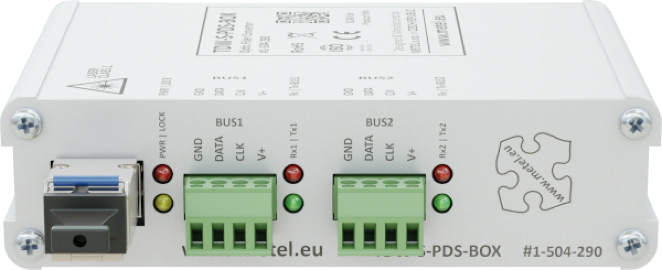
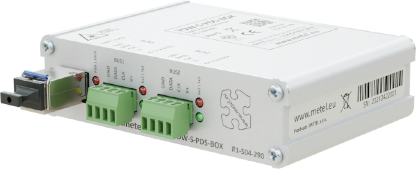
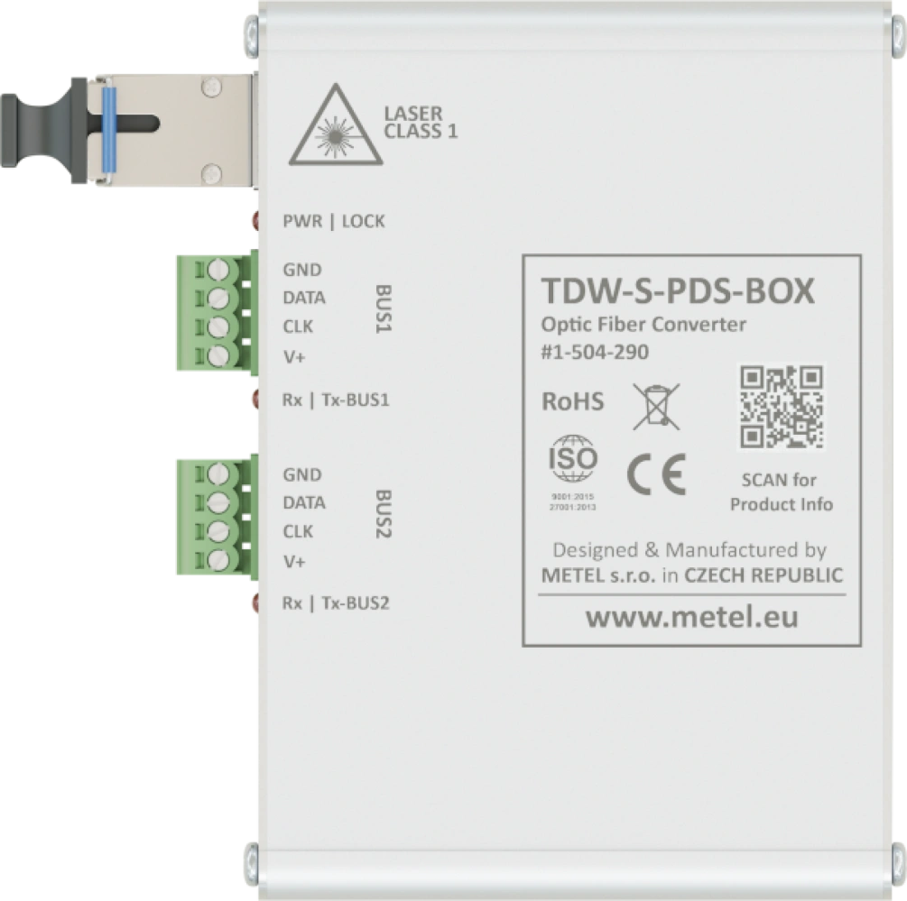
TDW-S-PDS-BOX/12
MM/SM universal optical converter for system buses ABI, MB SECURE, PARADOX EVO, SATEL INTEGRA. 1x SC/PC optical connector (CWDM), 2x data BUS, Surge protection, Digital modulation
Order code: 1-504-290
Availability: Full-scale production
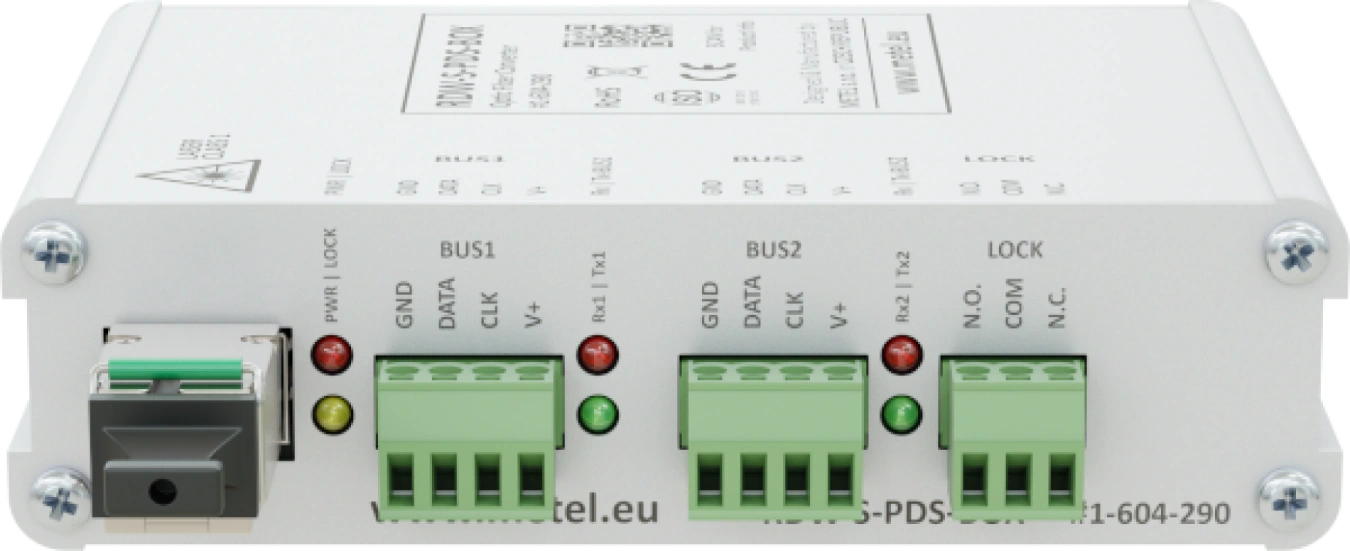
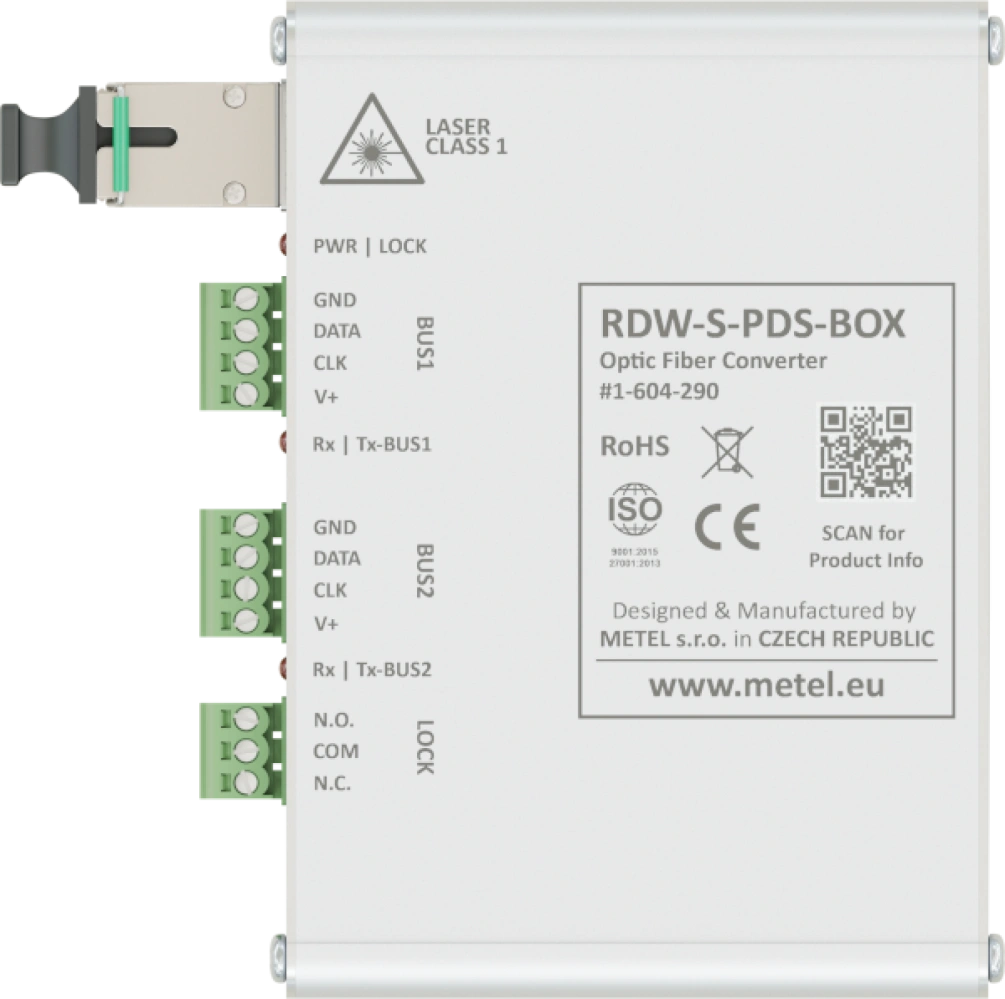
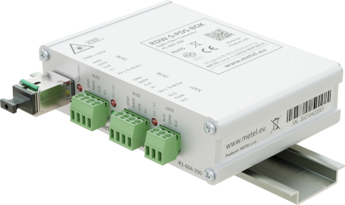
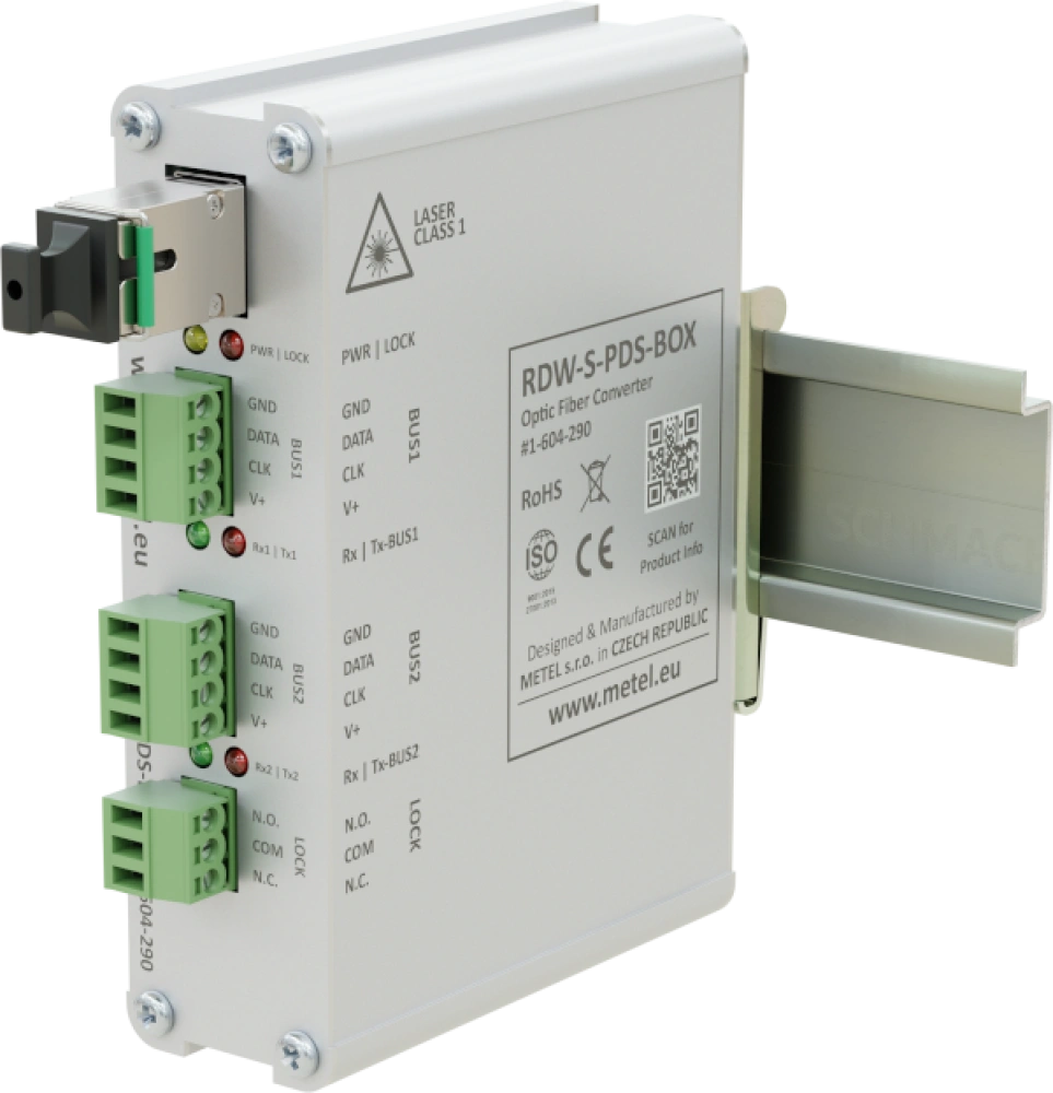
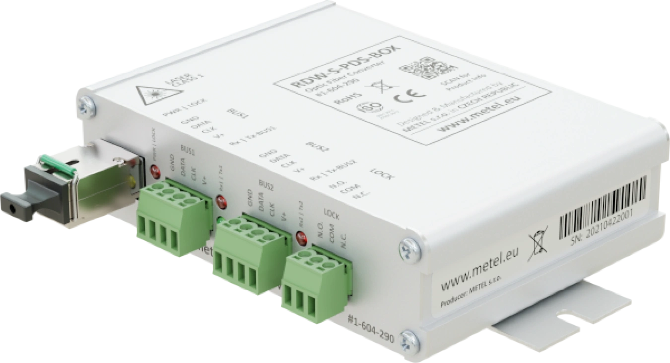
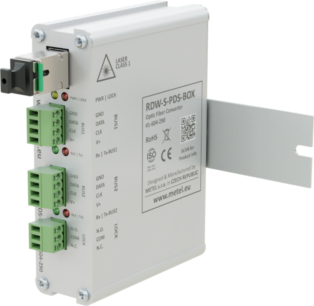
RDW-S-PDS-BOX/12
MM/SM universal optical converter for ABI, MB SECURE, PARADOX EVO, SATEL INTEGRA system buses. 1x SC/PC optical connector (CWDM), 2x data BUS, 1x LOCK NO/NC relay, Surge protection, Digital modulation
Order code: 1-604-290
Availability: Full-scale production
Specifications
Technical parameters
| DATA BUS | |
|---|---|
| Count | 2 |
| Surge protection | 600 W waveform 10/1000 μs |
| OPTICAL PORT | |
|---|---|
| Optical power | -14 - -8 / -10 - 0 dBm (SM / MM) |
| Sensitivity | -31 dBm |
| Connector | SC/PC |
| OPTICAL RANGE | |
|---|---|
| ABI | 5/10 km (MM/SM) |
| MB SECURE | 5/10 km (MM/SM) |
| PARADOX EVO | 5/5 km (MM/SM) |
| SATEL INTEGRA | 5/5 km (MM/SM) |
| LOCK RELAY | |
|---|---|
| Count | 1x on RDW |
| Max. Load | 125 VAC / 0.5 A or 60 VDC / 0.3 A |
| Type of contact | Switching |
| POWER | |
|---|---|
| Input voltage range | 10 - 20 VDC |
| Power consumption | Max. 1.5 W |
| Surge protection | 600 W waveform 10/1000 μs |
| ENVIRONMENT | |
|---|---|
| Operating temperature | -40 - +70 °C |
| Storage temperature | -40 - +70 °C |
| Humidity | Max. 95 % |
| MECHANICAL | |
|---|---|
| Weight | 0.22 kg |
| Dimensions - h / w / d | 30 x 110 x 97 mm |
Standards and protocols, EMC and safety
| EMC and safety | ||
|---|---|---|
| EN 55032 | EMC of multimedia devices - emission requirements | |
| EN 55035 | EMC of multimedia devices - immunity requirements | |
| EN 62368-1 | Safety requirements of Information technology equipment | |
| EN IEC 63000 | The Assessment Of Electrical And Electronic Products With Respect To The ROHS | |
| EN 50131-1 | 4 | Alarm systems - system requirements |
| EN 50131-3 | 4 | Alarm systems - control panels |
| EN 61000-6-2 | Immunity - industrial environment | |
| EN 61000-4-2 | 4 kV | Air discharge |
| EN 61000-4-2 | 4 kV | Contact discharge |
| EN 61000-4-3 | 10 V/m | Radiated HF field |
| EN 61000-4-4 | 500 V | Bursty |
| EN 61000-4-5 | 500 V | Shock impulses |
| EN 61000-4-8 | 30 A/m | Magnetic field |
| EN 61000-4-11 | Short-term power dips and outages | |
| Standards and protocols | |
|---|---|
| Communication bus | Satel Integra, M-BUS (ABI systems), BUS 2 (MB SECURE systems), paradox EVO |
Downloads
Package contents
- Converter with SFP module
- DIN rail mounting kit
- Mounting kit for mounting on a flat surface
FAQ
Can these converters be used for new types of DSC POWER NEO control panels?
No, they can't. These converters are designed for control panel types with DSC POWER designation. We recommend using xDW-S-4C converters that are compatible with the DSC POWER NEO control panel.
What are the requirements for SATEL cabling?
For electrical connection it is recommended to use straight unshielded cable between devices in the system (the use of twisted pair, UTP, STP, FTP is not suitable). If you use twisted pair cable, remember that the signal wires DTM and CKM / DT1 and CK1 / DT2 and CK2 (data and clock) must not run through one pair in the cable.
The choice of cables for the power supply should be selected so that the voltage drop between the power supply and the device being powered does not exceed 1 V compared to the output voltage of the power supply.
To guarantee the correct functionality of the system components, it is important to make sure that the resistance and capacitance of the signal cables is the lowest possible. If the distance between devices is large, it is a good idea to use several wires in parallel for each signal to reduce the resistance of the wire, but such a connection will lead to an increase in the capacitance of the wire. Too high resistance or capacitance of cables connected to keypads or expansion modules may cause communication problems with these connected devices (e.g., the control panel will not be able to identify the devices, communication failure of these devices will be reported, etc.).
When selecting cable lengths, follow the recommendations for each type of device.
When installing the cabling, remember that sufficient distance must be maintained between the low-current cables and the 230 VAC power cables. Avoid having signal cables in close proximity to power cables.
Note: The text has been taken from the SATEL control panel installation manual.