
Alarm/digital inputs on G-series switches
Alarm inputs
Last updated: 18 August 2026
FW version: 9.2090.17112 and above
SIMULand.v4 version: 26.8.18.xxxx and above
Device type: 2G-2C.0.8.G-BOX-PoE-PP
Description
The switch supports inputs in ‘balanced’ alarm loop mode. The measured value ranges from 0 to 30,000 ohms. It can efficiently forward the readings via the SNMP protocol.
Limitations
Currently, there is NO event implemented that would trigger automatic actions.
Alarm loop configuration is available via SNMP or in the SIMULand.v4 application; the alarm loop cannot currently be configured via the CLI.
Example: Detection of a 230 VAC power failure and a battery fault
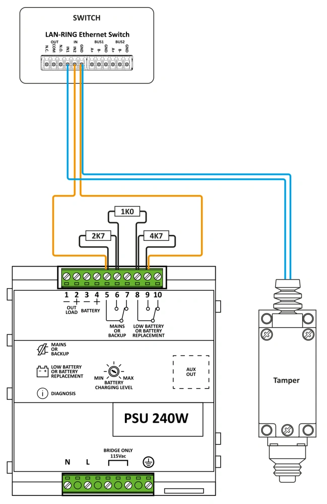
- Measurement: The alarm relay outputs of the backup power supply are balanced using resistors. The balanced loop is connected to the switch’s input, and the switch is able to reliably distinguish between the following states:
- open loop
- normal state
- 230 VAC failure
- battery fault
- short-circuit in the loop - Reading: The LAN-RING switch continuously measures the balanced loop values.
- Storage: In the event of a change, the switch immediately sends an SNMP trap containing the current value to the control unit (IPLOG), where the data is stored in a MySQL database.
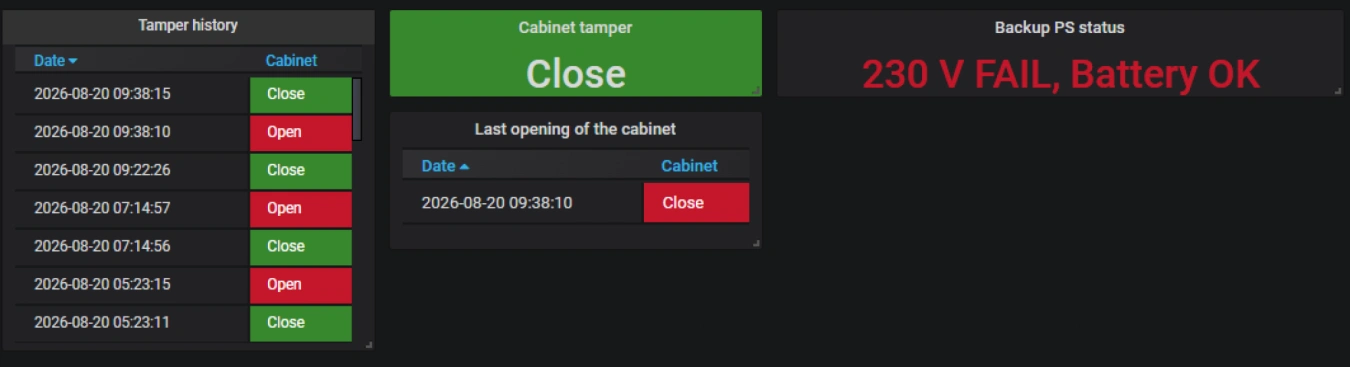
- Display: The measured values are clearly displayed in real time in the Grafana application.
Digital inputs
FW version: 4.1890.15912 and higher
SIMULand.v4 version: 25.03.01.xxxx and higher
Device type: All G-series switches equipped with digital/alarm inputs
Description
The switch supports inputs in digital mode – on/off. It can efficiently forward the read values via the SNMP protocol. Digital input configuration is available via SNMP, in the SIMULand.v4 application or via the CLI.
Limitations
Currently, there is NO event implemented that would trigger automatic actions.
Example: Detection of a switchboard being opened
- Measurement: A cabinet tamper is connectedto the switch’s digital input.
- Reading: The LAN-RING switch continuously detects the closing and opening of the potential-free input.
- Logging: In the event of a change, the switch immediately sends an SNMP trap containing the current value to the control unit (IPLOG), where the data is stored in a MySQL database.
- Display: The measured values are clearly displayed in real time in the Grafana application.
Wiring diagram
Grafana